Instrument Cluster
Instrument Cluster
General information
The clusters themselves come in various trims, which have differences ranging from tiny to severe. Please refer to the list below for some of the differences between the different models:
| Cluster | Used in | Notes |
|---|---|---|
| Low | Forte/Futura/S/SR | Only contains rev, speedometer, temp and fuel gauges. Base model cluster |
| Pursuit | Police Vehicles | police-modified low cluster with 240km/h max speed, marks every 2km/h, and programmable speedometer (for different tyre sizes) |
| Mid | XR6/XR8 | all base gauges as well as oil pressure and battery voltage gauges. increased max reading to 240km/h (V8 only?) and gear selector indicator |
| High | Fairmont/Fairlane/LTD | all mid cluster features, an upgraded Odometer display, more specific door ajar indicator, and additional warning lights (alternator, TCS, washer fluid, etc.) |
Changing between cluster types
When changing between instrument cluster types, the following should be put into consideration:
-
The pinouts between low and high clusters are different, and require moderate rewiring to retrofit
Resources on rewiring not available on this site as not yet attempted
-
Placing high clusters in base/low models is ill-advised, due to lower model vehicles and looms having the following functions missing or modified:
- TCS - Not present
- Low Coolant - May not be present
- Gear selection display (where fitted) - not present
- Door open display - Simplified - light for any door open present, but no wiring for individual doors
Pursuit Cluster - Speedometer Calibration
Pursuit clusters are not only sought after as they are, in theory the rarest type of speedometer available for the AU Falcon, they are also useful for on-the-fly speedometer calibration, allowing for much more flexibility with wheel sizes and differential ratios.
The calibration mode allows for 10% of calibration in either direction (so 90-110% stock) and increments about 0.5% each button press. for more than this, you will need to change some or all of tyre size, transmission gearing and differential ratios. A speedometer calibration tool is available on this site.
- do the following depending on your series of CLUSTER:
- For S1 Clusters, switch the ignition key to the “On” position (second click from off), press and hold the odometer stalk button for 5 seconds and release
- For S2/3 Clusters, hold the odometer stalk button, turn the ignition key to the “On” position (second click from off), continue holding the button for 5 seconds, then release
- switch the ignition key to the “On” position
-
after following the previous step, ensure the word
SPEEDO 0.0shows up on the instrument clusterThe 0.0 in the display stands for the default, if you have changed yours previously it will be a different number
- press the instrument cluster button until the number next to
SPEEDOon the display is at the desired value, noting:- A short press (less than 1 second) will increase the number by 0.5
- A longer press (less than 5 seconds) will decrease the number by 0.5
- press and hold the instrument cluster button for about 7 seconds to exit calibration mode
- done
Service spanner (where fitted)
On models with a service spanner in the instrument cluster, you can disable it by following the steps below:
- turn the ignition to the “On” position (2 clicks from off)
- press and hold the instrument cluster odometer stalk for 10 seconds, then release
- done
Plug types
The plugs in the back of the instrument cluster all seem to be MULTILOCK 040 II connectors, seemingly manufactured by a company called TE Connectivity. Part information varies according to which specific plug is desired.
IMPORTANT
note that the plugs are MULTILOCK 040 II and not MULTILOCK 040, as there are subtle differences between the 2 versions
Information is specific to low model clusters due to project only involving 1 S1 Forte cluster and 1 S1 Pursuit cluster to date
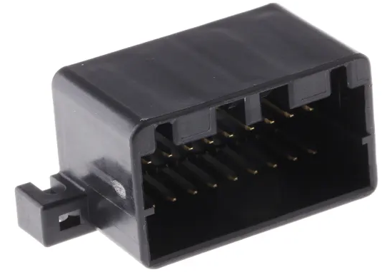
12 way plug - top plug behind fuel gauge side of cluster
| Name | Code | Notes |
|---|---|---|
| Male Connector Housing | 175965-2 | Loom end connector |
| Right Angle Through Hole Mount PCB Socket | 175974-2 | Cluster end connector, with right angle solder mounts behind |
Male connector image taken from RS Components product page Datasheet (only good picture of front found)
Female connector image taken from RS Components product page (3D model only known good image)
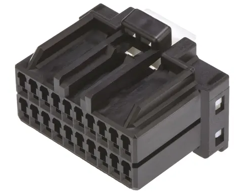
16 way plug - bottom plug behind fuel gauge side of cluster
| Name | Code | Notes |
|---|---|---|
| Male Connector Housing | 175966-2 | Loom end connector |
| Connector Socket | 175615-2 | Cluster end connector, with right angle solder pins behind |
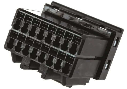
Male connector image taken from RS Components product page
Male connector image taken from RS Components product page
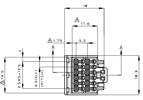
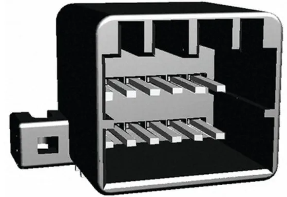
combination 28 way mount - possible solder replacement for entire fuel gauge side plugs on instrument cluster
| Name | Code | Notes |
|---|---|---|
| Right Angle PCB Socket | 1-175976-2 | UNTESTED |
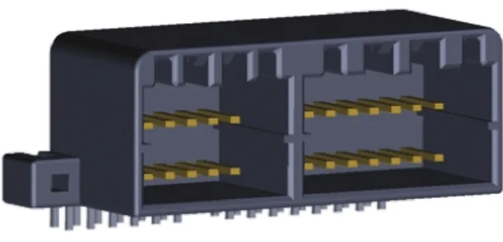
PCB Connector image taken from RS Components product page (3D model only known good image)
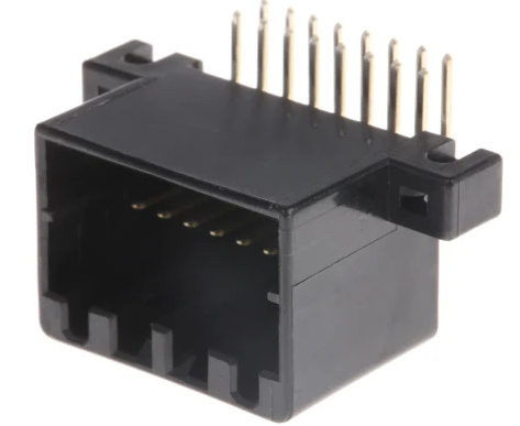
20 way plug - plug behind RPM gauge side of cluster
| Name | Code | Notes |
|---|---|---|
| Male Connector Housing | 175967-2 | Loom end connector |
| Connector Socket | 175975-2 | Cluster end connector, with right angle solder pins behind |
Male connector image taken from RS Components product page
Female connector housing image take from RS Components product page