Cabin Fuse Panel
Cabin Fuse Panel
This is a more technical page, if you are simply looking for vehicle-specific fuse and relay information or minimum required fuses, see HERE instead, and for general relay information, see HERE
This page is a half complete mess from an idea that went as well as a lead balloon. The only reason this page still exists is due to the time it took to create, and the hope that someone can make sense of anything discovered in here. Every attempt has been made to make the notes here legible, but this is not guaranteed.
the cabin fuse box has 11 individual electrical plugs that comprise it’s wiring, and as such the wiring has been divided as below per plug.
All diagrams assume that you are facing either the front or the back of the cabin fuse panel, with the relays at the top.
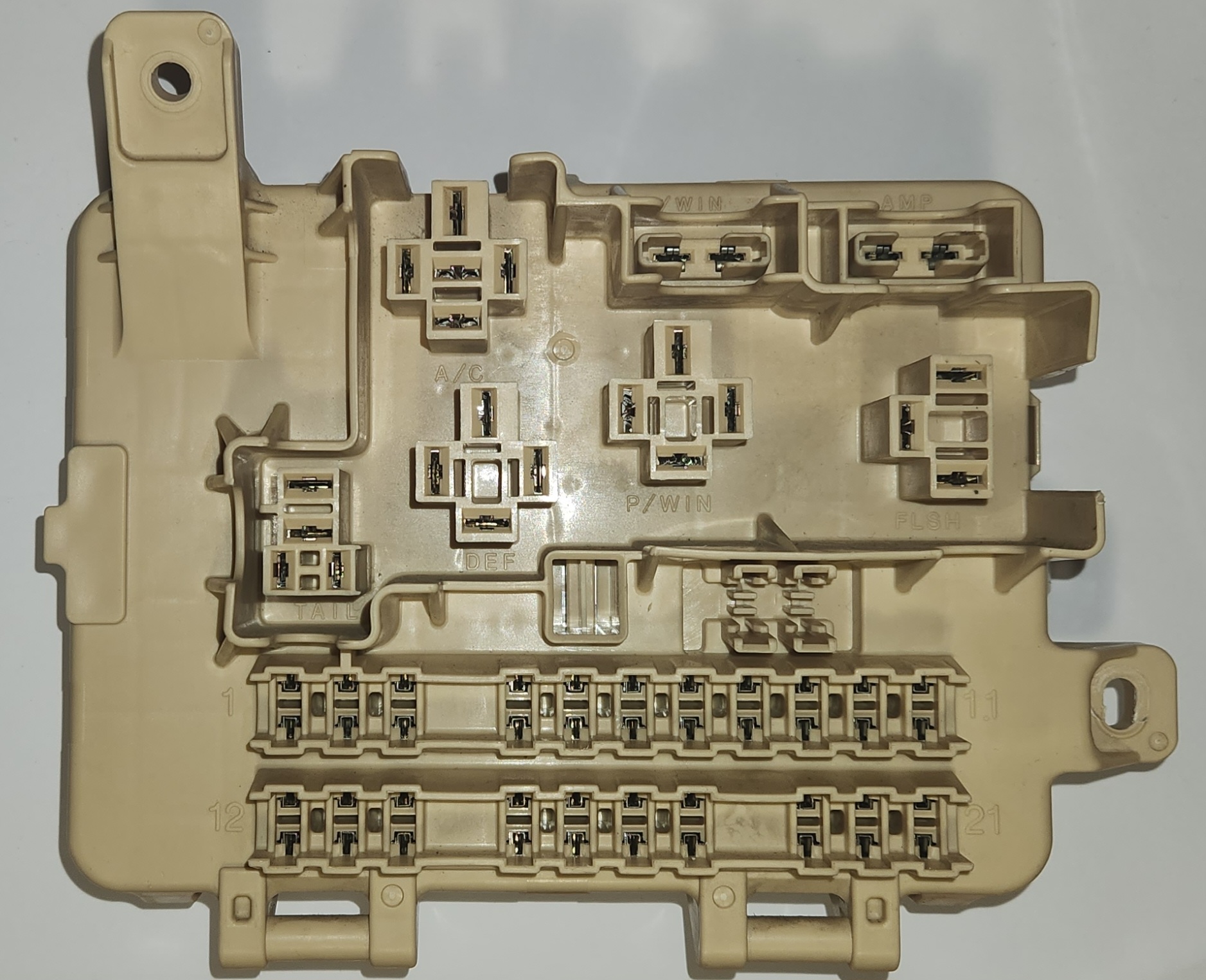
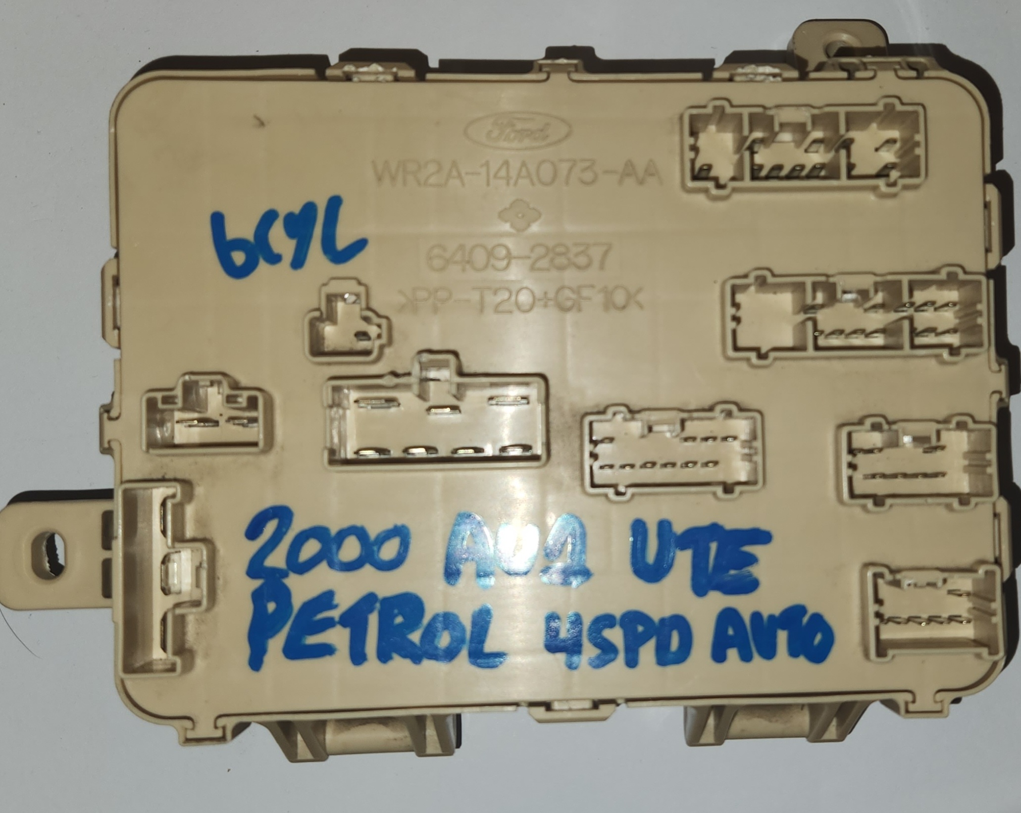
Pictures of how the fuse panel should be facing you from the front a rear respectively
Reading this guide
Use the legends table below to decipher what each code means. This was made in order to make more sense of the pins on both the front AND back of the cabin fuse box
| Code | Meaning | Notes |
|---|---|---|
Fx-y |
Fuse location by number index | requires below diagram or labelled cabin fuse panel. e.g. F1-1 for the top pin of fuse 1, F1-2 for fuse 1’s bottom pin, etc. (assume you are facing the cabin fuse panel with the relays at the top and the fuses down the bottom) |
Rx-y |
Relay pin location by index | requires guide below, e.g. R1-1 for the top pin of the A/C relay |
Fuse & Relay Connectors (Front)
These connectors are identifiable according to the annotated image:
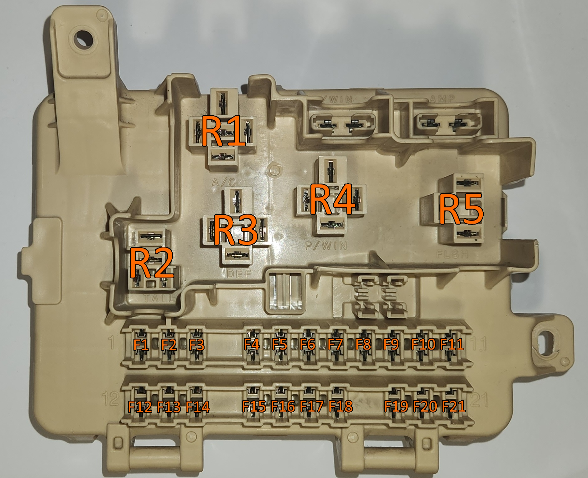
The P/WIN and AMP fuses are not marked on purpose, both because they are clearly marked AND because depending on the manual, these have different designations, which overlap with the existing fuses in the bottom
Main Fuse Cluster
Below is a layout of all fuse block pins:
F1-1 |
F2-1 |
F3-1 |
F4-1 |
F5-1 |
F6-1 |
F7-1 |
F8-1 |
F9-1 |
F10-1 |
F11-1 |
|
F1-2 |
F2-2 |
F3-2 |
F4-2 |
F5-2 |
F6-2 |
F7-2 |
F8-2 |
F9-2 |
F10-2 |
F11-2 |
|
F12-1 |
F13-1 |
F14-1 |
F15-1 |
F16-1 |
F17-1 |
F18-1 |
F19-1 |
F20-1 |
F21-1 |
||
F12-2 |
F13-2 |
F14-2 |
F15-2 |
F16-2 |
F17-2 |
F18-2 |
F19-2 |
F20-2 |
F21-2 |
relay 1 - A/C Relay
This relay is a the only full-sized 5 way relay connector present in the cabin fuse panel. For the following assume the following layout:
R1-1 |
||
R1-2 |
R1-3 |
R1-4 |
R1-5 |
||
Pin definitions
| Index | Relay Terminal Number |
|---|---|
| R1-1 | 87 |
| R1-2 | 85 |
| R1-3 | 87a |
| R1-4 | 86 |
| R1-5 | 30 |
More information: Relays
relay 2 - TAIL Relay
This relay is a half-size 4 way relay connector. For the following assume the following layout:
R2-1 |
|
R2-2 |
|
R2-3 |
R2-4 |
Pin definitions
| Index | Relay Terminal Number |
|---|---|
| R2-1 | 2 |
| R2-2 | 1 |
| R2-3 | 5 |
| R2-4 | 3 |
These half-size relays are generally 5-way relays rather than 4-way, however in the Original part, the pin between
R2-1andR2-2(relay terminal pin number 4) has been cut off
More information: Relays
relay 3 - DEF Relay
This relay is a full-size 4 way relay, for the following assume the following layout:
R3-1 |
||
R3-2 |
R3-3 |
|
R3-4 |
||
Pin definitions
| Index | Relay Terminal Number |
|---|---|
| R3-1 | 87 |
| R3-2 | 85 |
| R3-3 | 86 |
| R3-4 | 30 |
More information: Relays
relay 4 - P/WIN Relay
This relay is a full-size 4 way relay, for the following assume the following layout:
R4-1 |
||
R4-2 |
R4-3 |
|
R4-4 |
||
Pin definitions
| Index | Relay Terminal Number |
|---|---|
| R4-1 | 87 |
| R4-2 | 85 |
| R4-3 | 86 |
| R4-4 | 30 |
More information: Relays
relay 5 - FLSH Relay
This relay is a 3 way flasher relay, for the following assume the following layout:
R5-1 |
R5-2 |
R5-3 |
Pin definitions
| Index | Relay Terminal Number |
|---|---|
| R5-1 | 49a |
| R5-2 | 31 |
| R5-3 | 49 |
More information: Relays
Connector Plugs (Rear)
These plugs are identifiable according to the annotated image below
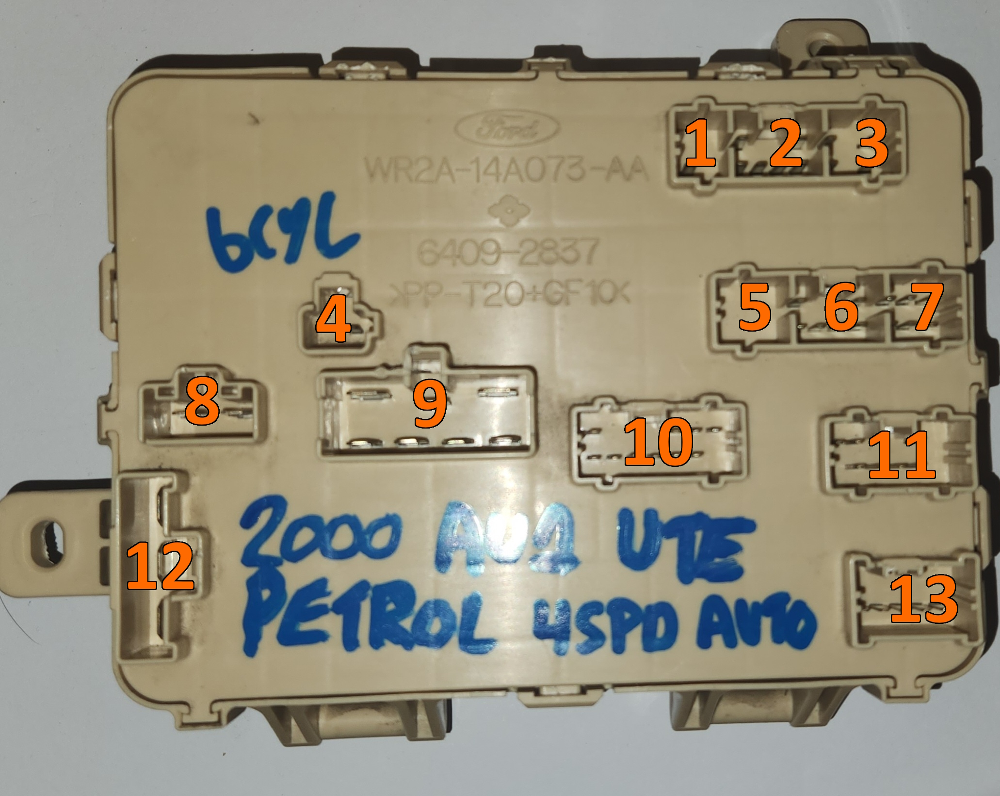
plug 1 - 1-way connector
this plug contains a single pin, noted as 1-1, which has continuity with F21-2
plug 2 - 6-way connector
For the following assume the following plug layout:
2-1 |
2-2 |
||
|---|---|---|---|
2-3 |
2-4 |
2-5 |
2-6 |
These pins have continuity with the following:
| pin | continuity |
|---|---|
| 2-1 | R1-2 |
| 2-2 | R5-1 |
| 2-3 | R5-3 |
| 2-4 | Circuit 3 |
| 2-5 | R1-3 |
| 2-6 | Circuit 5 |
plug 3 - 4-way connector
For the following assume the following plug layout:
3-1 |
3-2 |
|
|---|---|---|
3-3 |
3-4 |
These pins have continuity with the following:
| pin | continuity |
|---|---|
| 3-1 | R3-1 |
| 3-2 | Circuit 4 |
| 3-3 | left pin - AMP fuse |
| 3-4 | F14-2 |
plug 4 - 1-way connector
This plug has a single pin, noted as 4-1, which has continuity to Pin R4-1
plug 5 - blank
This plug does not have any connectors in the Forte models
This may be different in other models, information limited as project only involved Forte cabin fuse boxes
plug 6 - 6-way connector
For the following assume the following plug layout:
6-1 |
6-2 |
||
|---|---|---|---|
6-3 |
6-4 |
6-5 |
6-6 |
These pins have continuity with the following:
| pin | continuity |
|---|---|
| 6-1 | F9-2 |
| 6-2 | Circuit 5 |
| 6-3 | R3-2 |
| 6-4 | F10-1 |
| 6-5 | connected to pin 6-4 |
| 6-6 | Circuit 4 |
plug 7 - 6-way connector
for the following assume the following plug layout:
7-1 |
7-2 |
7-3 |
|---|---|---|
7-4 |
7-5 |
7-6 |
These pins have continuity with the following:
| pin | connectivity |
|---|---|
| 7-1 | F1-1 |
| 7-2 | F12-2 |
| 7-3 | Circuit 4 |
| 7-4 | F19-2 |
| 7-5 | F19-2 |
| 7-6 | F5-2 |
plug 8 - 2-way connector
for the following assume the following plug layout:
8-1 |
8-2 |
These pins have continuity with the following:
| pin | continuity |
|---|---|
| 8-1 | R1-1 |
| 8-2 | Circuit 6 |
plug 9 - 7-way connector
Plug 9 is unique as it has 2 different pin sizes within the plug housing. There are 3 pins on the top row and 4 on the bottom, as below:
9-1 |
9-2 |
9-3 |
|||||||||
9-4 |
9-5 |
9-6 |
9-7 |
||||||||
These pins have continuity with the following:
| pin | continuity |
|---|---|
| 9-1 | right pin - P/WIN fuse |
| 9-2 | F18-2 |
| 9-3 | Circuit 7 |
| 9-4 | R1-1 |
| 9-5 | Circuit 2 |
| 9-6 | R4-1 |
| 9-7 | Circuit 6 |
plug 10 - 10-way connector
for the following assume the following plug layout:
10-1 |
10-2 |
10-3 |
10-4 |
|||
|---|---|---|---|---|---|---|
10-5 |
10-6 |
10-7 |
10-8 |
10-9 |
10-10 |
These pins have continuity with the following:
| pin | continuity |
|---|---|
| 10-1 | F7-1 |
| 10-2 | F2-2 |
| 10-3 | Circuit 3 |
| 10-4 | R2-3 |
| 10-5 | R4-2 |
| 10-6 | F3-1 |
| 10-7 | F6-1 |
| 10-8 | F4-1 |
| 10-9 | F3-1 |
| 10-10 | F5-2 |
plug 11 - 7-way connector
for the following assume the following plug layout:
11-1 |
11-2 |
11-3 |
|||
|---|---|---|---|---|---|
11-4 |
11-5 |
11-6 |
11-7 |
These pins have continuity with the following:
| pin | continuity |
|---|---|
| 11-1 | Circuit 11 |
| 11-2 | Circuit 3 |
| 11-3 | F12-2 |
| 11-4 | F14-1 |
| 11-5 | Circuit 4 |
| 11-6 | Circuit 4 |
| 11-7 | F13-2 |
plug 12 - 3 way connector
for the following assume the following layout:
12-1
12-2
12-3
|
These pins have continuity with the following:
| pin | continuity |
|---|---|
| 12-1 | Circuit 8 |
| 12-2 | Circuit 9 |
| 12-3 | Circuit 10 |
plug 13 - 6-way connector
for the following assume the following layout:
13-1 |
||||
|---|---|---|---|---|
13-2 |
13-3 |
13-4 |
13-5 |
13-6 |
These pins have continuity with the following:
| pin | continuity |
|---|---|
| 13-1 | F19-2 |
| 13-2 | F16-1 |
| 13-3 | F20-1 |
| 13-4 | Circuit 4 |
| 13-5 | Circuit 4 |
| 13-6 | R3-1 |
Additional Circuits
Circuit 1 - P/WIN
There is a direct link between the following pins, related to the Power Windows circuit
Circuit 2 - DEF
There is a direct link between the following pins, related to the Rear Window Defrost circuit
Circuit 3 - TAIL
There is a direct link between the following pins, related to the Tail light circuit
Circuit 4 - A/C & FLSH
There is a direct link between the following pins, related to the FLSH and A/C circuits:
- R5-2
- R1-4
- connector pin
3-2 - connector pin
7-3 - connector pin
7-6 - connector pin
11-6 - connector pin
11-7 - connector pin
13-4 - connector pin
13-5 - connector pin
13-6
Circuit 5 - Misc. Fuses & Connector Pins No. 1
There is a direct link between the following pins, related to a single fuse, and multiple rear connector pins:
Circuit 6 - Misc. Fuses & Connector Pins No. 2
There is a direct link between the following fuse pins, related to multiple connector pins and multiple fuses:
Circuit 7 - Misc. Fuses & Connector Pins No. 3
There is a direct link between the following fuse pins, related to multiple connector pins and multiple fuses:
Circuit 8 - AMP
There is a direct link between the following pins, related to the Amplifier circuit
- R1-5
- Right pin - AMP fuse
Circuit 9 - Misc. Fuses
There is a direct link between the following pins, related to a single connector pin and multiple fuses:
Circuit 10 - P/WIN
There is a direct link between the following pins, related to the Power Window Circuit, one connector pin, and multiple fuses:
- Right pin - P/WIN fuse
- F15-2
- F16-2
- connector pin
12-3
Circuit 11 - TAIL
There is a direct link between the following pins, related to the TailLights relay and a fuse: